
Another CORONA project. Designing an Arduino based battery tester for my e-mobility projects.
I suggest this Kraftwerk Song as background music for the blog.
I looked for months in the internet (Amazon, Conrad, Alibaba..) for a universal battery tester that can be used to test the capacity of batteries with voltages from 3.2V, 6V, 12V, 48V all the way to 72V, which I need for my various e-mobility projects. I did not find one, except for some specialized, heavily overpriced testers, and they were still limited in options. And I needed a COVID restriction project that allowed me to keep my sanity while going through all sort of COVID related Bullenscheisse. So I decided to develop one myself. The beauty of designing your own device is that you get exactly what you want, and can modify it and add features. Ultimately I could even sell it since there seems to be no such product on the market.
I have chosen the Arduino as a platform for the development. Powerful enough, very commonly used, not as complex as an Raspberry Pie.
This blog just outlines the journey.
Initial specs for Version 1
Version 1 is just aiming at 12V batteries, I have lots of them, in Magayon II, at the house in the self made UPS and in all vehicles. Version 1 will be the proof of concept and provide learnings, which, together with modifications needed for the other voltages, will then be included in Version 2.
Specs for Version 1 include:
- Variable load resistors for simulating different discharge currents. Load resistors will be external, connected via a DIN connector, also for easier heat management.
- Constant discharge, continuous monitoring of battery voltage, discharge current and temperature of the load resistors to avoid them overheating
- Calculation of discharge time, and capacies in Wh and in Ah
- Rechargeable battery operation for the controller to address the still frequent brownout problems in the Philippines
- Modular load resistors to be able to use it for very low capacity batteries (e.g. the Honda Dax) to very high ones (House UPS)
- Different modes of operation: 1. Setup, 2. Test ongoing, 3. Test completed successfully, 4. Aborted by user, 5. Aborted because of error.
Developing the circuit
I still had an Arduino Nano on stock, which I wanted to take back to the Philippines. A visit to Conrad in Stuttgart and some online orders completed the basics components I need for the project. And I got a beautiful vintage Teko housing, from an Italian company that already existed when I did my vocational training at Bosch in the 1970s. Some good things seem to stay forever.
Progress
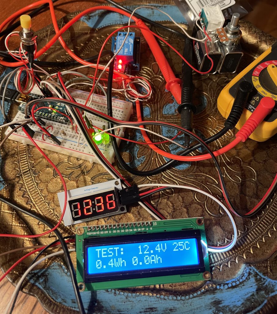
Battery voltages from 0-18 V are first simulated with to 9V battery blocks connected in series and equipped with a potentiometer for adjusting the voltage. My workshop is my parent’s dining table, where I stay occasionally while waiting for my visa and travel arrangements. Since I did not have any tools here anymore I bought an aluminium suitcase and basic tools, including soldering iron and butane fired heat gun for heat shrinkable tubes. So ready to do some basic prototyping.
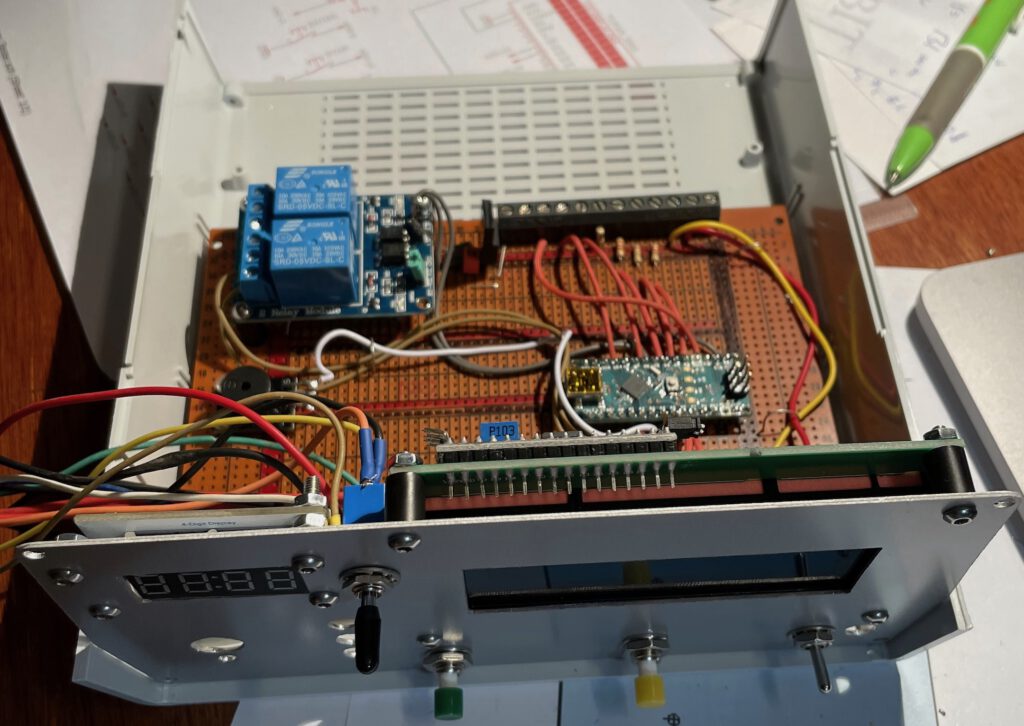
Key elements for the circuit are:
- Arduino Nano, to be replaced by Arduino Every in the final version
- 4×7 Segment display
- LCD display with 16 characters in two lines, I2C interface.
- Relais card
- Several switches and LEDs
- Single channel DS18B20 temperature sensor
- Lots of standard electronics components
An then I got to work in the evenings, daytime is still regular job time.
A Sketchup design of the front panel is also ready.
Using a 4 line display
December 7, 2021.
I found the display area a bit limiting and therefore looked for another display with 4 lines with 20 characters per line. It cost less than 10 Euro and arrived after two days after placing the order. I just connected it instead of the 2 line display. Miraculously it worked straight away, including the additional 4 characters per line and the two additional lines. I was not sure whether the driver would work, but it did. Fantastic. So now the whole thing goes in a box for taking with me on a flight to the Philippines where I will finish the project and put the battery tester to good use. Need to change the dimensions for the cut-out of the front panel.
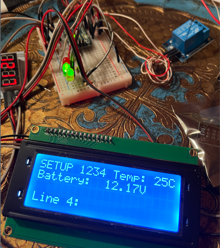
Tips:
1.) Use the LiquidCrystal_I2C.h library.
2.) Make sure the jumper on the I2C board is bridging the two pins on the side, this turns the backlight on. If it is missing the LDC display is blank
3.) if the LCD display is lt up, but does not show anything, play around with the potentiometer on the I2C board, which adjusts the brightness/contrast of the backlight.
Optimizing code
December 9: Traveling during COVID times is difficult. I ended up spending one night at the Hilton in Frankfurt Airport. Usually I would have gone out for a beer, but that is also difficult and I did not want to take chances test positive tomorrow. So I ended up spending the evening in the hotel room with optimizing the code for the 4 line display.
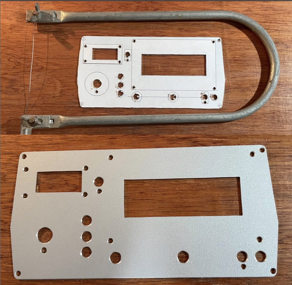
The enclosure
After moving back to Los Banos, two weeks of home quarantine are required. Home office during the day, ample time during the evening to work on the enclosure. First thing is the front panel. Design nowadays is easy with Sketchup, compared to my BOSCH times when we had to draw everything manually. Drilling the holes was next and then cutting the rectangular openings with the jig saw. It ended up looking quite professionally.
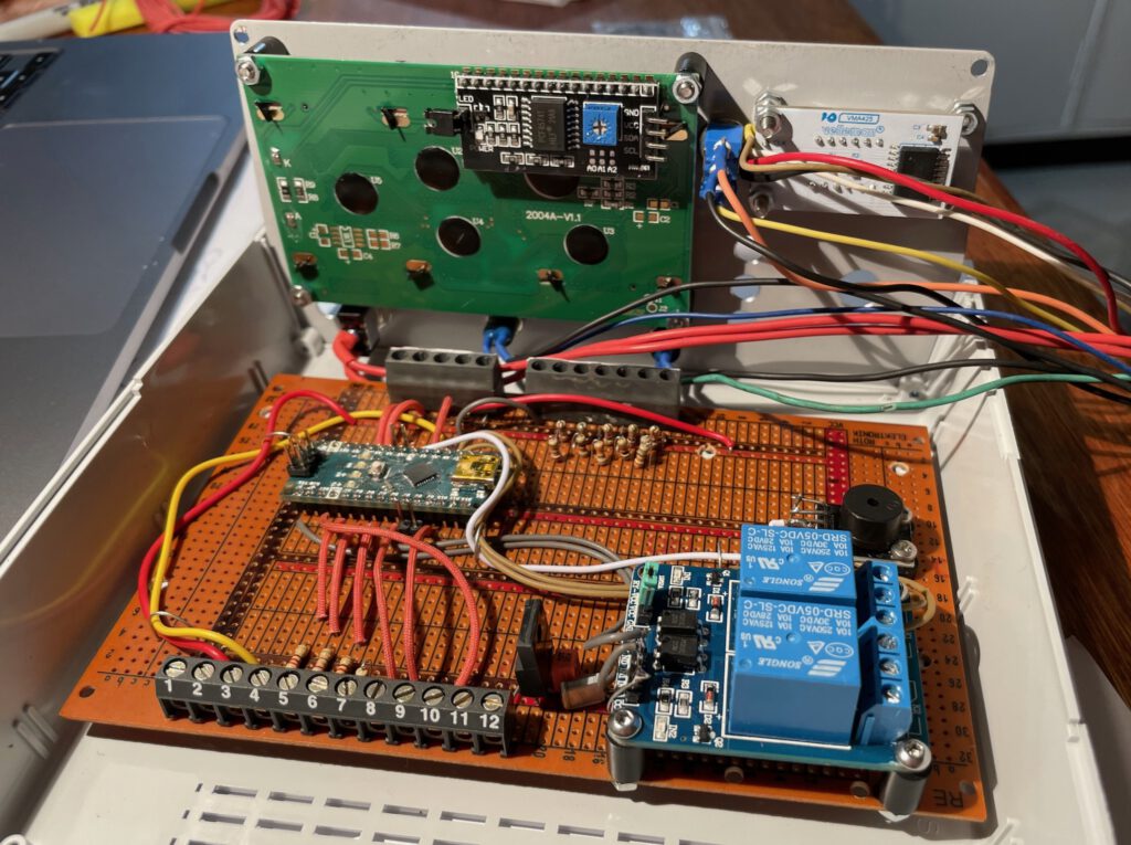
Next step was the PCB. It should be big enough for extensions so I used a Europe format board. Hard wiring the Arduino and the other components took one evening. Still waiting for some parts that I did not have in my stockpile (LED brackets for example), but it looks promising.
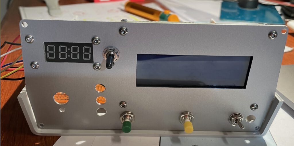
I used to label front panels with Letraset transferrable lettering, but that does not exist anymore, you can get some sheets on ETSY but they are terribly expensive, besides they are quite sensitive. So I need to find another way for labeling the buttons and components.
I decided to do the hardware for later versions together with the first pilot. That way I won’t have to do too much additional soldering later on. Some questions remain regarding the multi voltage use:
- How to protect the analog input channel for the battery voltage from accidental overvoltage (5V allowed only at an Arduino input channel). Zener Diode? That will work with all measuring ranges except for the 3.2V (single LiFePo4 cell) since that input would go straight to the AD channel. It would fry the Zener diode at higher voltages. Maybe reduce resolution and have a resistor in series.
- Power supply. I would like to use two LiIon cells, around 7V. How to charge it? I would need a BMS.
Completing the circuit and testing
December 26
I am still lacking the power supply, the 220V connector and the rotating button for selecting the battery voltage, but otherwise the device as good as complete.