Part 1: Designing, constructing and prototyping the motor
The first attempt
Blog started in June 2023
The first attempt to electrify the drive for Magayon II led to me importing the first Torqeedo Travel 1003CL outboard motor from Germany to the Philippines in October 2017. I had contacted the Torqeedo company in Starnberg and wanted them to ship me a unit. But then they said they were just in the process of discussing with Broadwater Marine to establish a local distributor in the Philippines and if I wanted to go though him they would make sure that I get a discount as a first customer to match the price in Germany. I got it for PHP 140k (US$ 2,770) including a remote throttle and a bluetooth interface for the smartphone, the successor model Toqeedo 1003CL costs now around US$ 2,500 without extras in Germany. It had 1,000 W power, so about 1/3 of the power of the motor in this project.
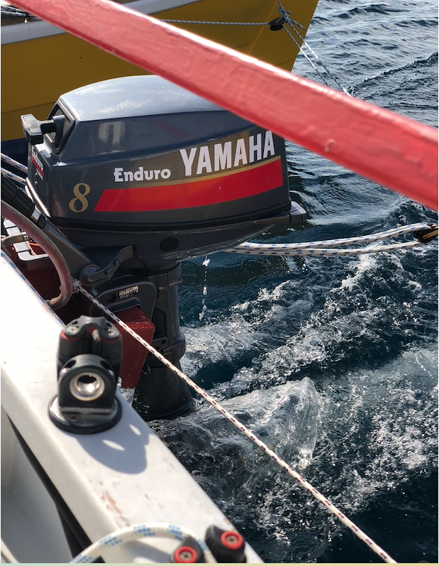
We used the motor a few times on Lake Taal and in Puerto Galera for testing, but on longer trips we preferred the 8h Yamaha Enduro two stroke gasoline guzzler because of the limited range of the Toqeedo battery. Then recently, during a stressful event, the Toqeedo including battery disappeared in the deep South China See.
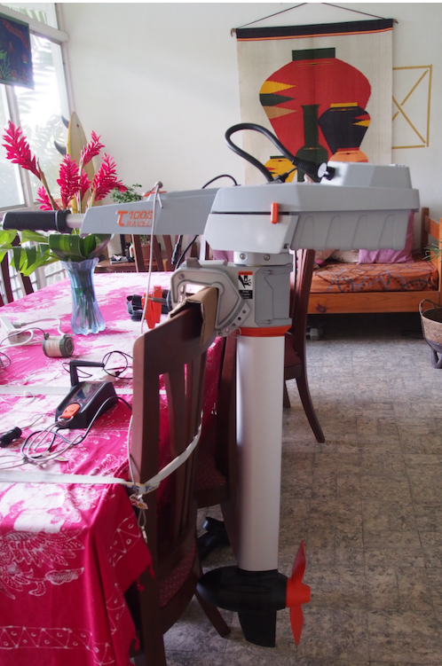
A shortcoming of the Torqeedo was that it uses a custom battery with its own interface, the battery can be swapped easily with a second one, but it is difficult to come up with own solutions for larger battery capacity. The larger Toqeedo Cruise models allow more flexibility, but at much higher cost and power.
A different approach this time
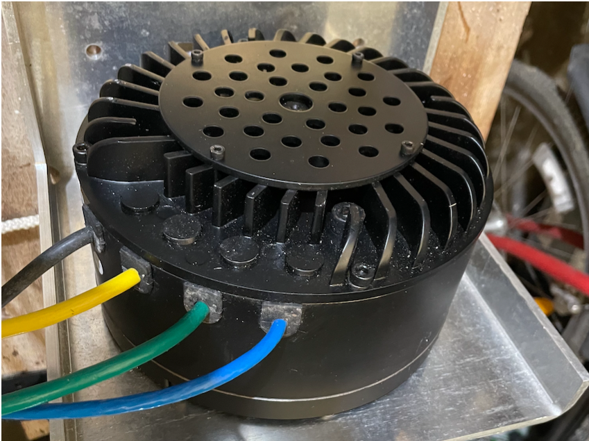
Separately I am working on converting a Yamaha DT125 motorcycle, and in that context I had bought 3 different types of electric motors, starting with a Gold Star motor sourced from an e-mobility company in Lithuania. I then found another motor from QS Motors that has a mechanical gear reduction built in so that it fits the motorcycle purpose a lot better. So the Gold Star motor became available for other other use. The motor has 3kW nominal power and around 5.3kW peak power, that should be more than enough for harbour and anchor maneuvers of Magayon II.
I started designing my own motor-drivetrain system based loosely on the idea of Thai Longtail drives of the boats on the Thai rivers. The idea was to have the motor in a box in Magayon II’s cockpit just behind the mast and then a tilt-able long shaft with the propeller at the end that could be lowered into the water by some still to be designed mechanical system. Hours of search of the internet for components (shaft, propeller, universal joints…) led to the conclusion that that would be a development project itself with lots of tinkering and testing and would need a lot of time. Some years ago, when our 8hp Yamaha outboard motor, initially borrowed from M. and recently donated to us, gave us one of its frequent troubles, I had thought about converting it, but since we need a working motor for the operation of the boat, I did not push through with the idea. But basically the idea sounded still good, even if there are efficiency losses due to the components (propeller, drive, bearings..) are designed for different specifications.
Some years ago the guys from the dive shop Mariposa on Pandan Island had converted a 15 hp outboard motor using an earlier model of the same electric motor I have now. They had used it in their shop operations but experienced some problems with overheating and corrosion of electric components. That showed that the idea, on principle, is feasible. The corrosion and cooling problems I can easily address technically.
Alternative Motor Donation
So the first challenge was to find a donor motor as an alternative to our current Yamaha Enduro 8.
Specs for the donor motor
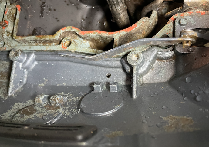
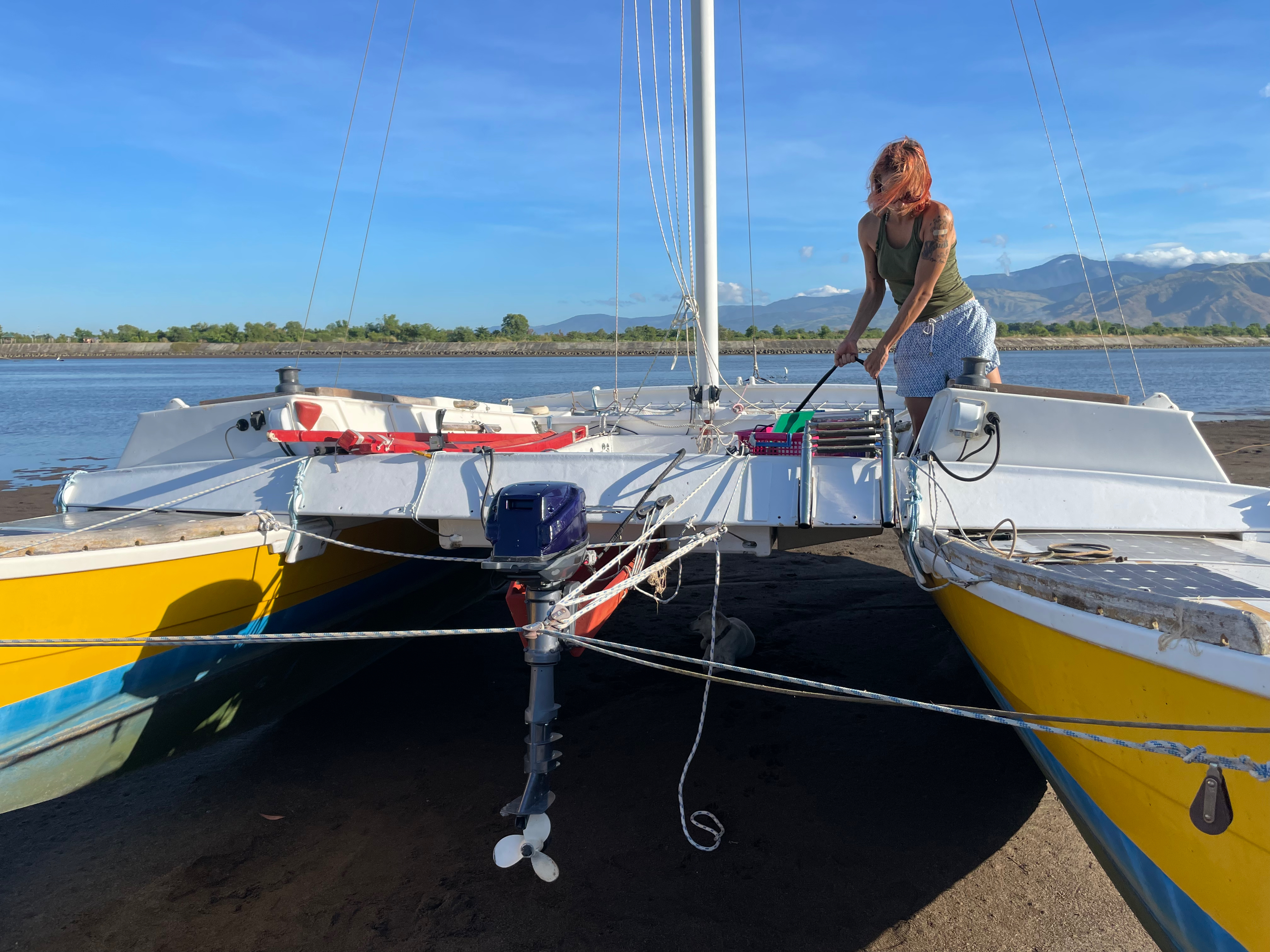
- The donor motor needs to be a long shaft so that it can be mounted at Magayon II’s existing outboard motor bracket ). See picture.
- It should not be too heavy, a 4-6hp motor would be ideal, 6-8hp still OK but 15hp is too big. We tried that. It bends the crossbeam.
- It needs to have sufficient space under the hood to accommodate the electric motor, controller and other components.
- The motor itself can be broken. But the shaft including the gear at the bottom should be in reasonable condition with minimum need for restoration.
- Last, but also important, it should be affordable.
- I planned have a look at an old Mariner motor next week. Looks promising.
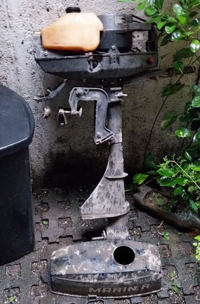
We got a donation of a 2.5 hp Mariner motor with broken power head from a Professor of a University in Manila. After taking the motor apart it turned out that it was too small to house the 3kW electric motor. And it needs some major overhaul of the shaft. Spare parts are ordered and the motor is reserved for the next project, converting a smaller unit, if the ongoing conversion is successful. See New Projects at the end of this blog.
Electric Boating? Is that Feasible?
It depends. For long distances not yet because there is just too little possibility to charge the batteries when on sea. Except you have a backup generator on board to charge the batteries in case of power needs. But for short distances / day tours and for doing the port and anchoring maneuvers with a sailboat and using the sails otherwise electric motors are already very feasible. Important is to maximize total system efficiency to get as far as possible with one battery load. Area for solar panels is limited on a boat.
Advantages
Electric motors have a lot of advantages over the fuel guzzlers:
- If the batteries are charged with power from renewable energy sources they are carbon neutral in operation
- They are clean, no messing around with fuel, oil, spillage, leakages to the sea, how I hated to fill the two stroke oil into the tank onboard
- They are quieter than the internal combustion engine
- Easy to handle and control
- Electric motors have full torque from the beginning starting at 0 rpm. (I will need to find out what that means in actual boat operation)
Constraints
For now there are still many disadvantages too
- Limited range
- Service centers? You can always find somebody who can fix a gasoline motor…
- Sensitivity of electric components to salt water
- ….
Charging Options
There are many options to re-charge the batteries:
- Land connection when the boat is docked at a pier. This is obviously the fastest option but not available when blue water sailing.
- Photovoltaic solar cells are a good option, but the space on a boat to place them is usually limited. On Magayon we have 4 solar panels with a total of 200W installed, there could be space for another 200W, but that would only work for long term charging, e.g. when the boat is anchored for several days
- Wind generators are quite common on bigger boats that circumvent the world. Not sure whether there are small options that could be used on Magayon II, will need to explore. Their charge power would also be limited.
- Recuperation when sailing. This is on theory possible. The Controller would need to support this. I will definitely explore that option.
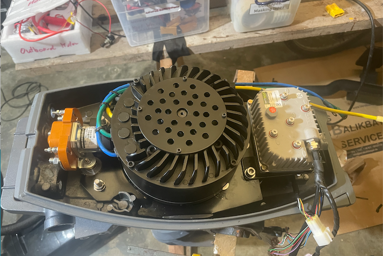
The Components
Compared to a motorbike conversion where you have to consider brakes and the 12V system parallel to the high voltage motor system, an electric marine drive is quite simple. It requires only the motor, controller, battery and very few other components like the speed controller / joystick, fuse and emergency off switch.
Motor
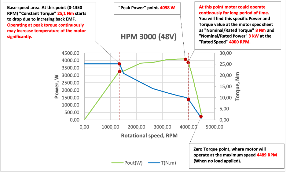
The Gold Star motor is air cooled and has 3kW nominal power at around 4,000 rpm. Operating voltage is 48V. Maximum power is around 4.1kW at around 3,800 rpm. The power and torque characteristics curve is very different from a gas guzzler, maximum torque of 25.1 Nm from zero up to about 1,350 rpm, then the torque drops due to increasing back EMF. That means that I probably need a different propeller, which provides more force at low speeds, which will be a challenge to get, since there are only two different propellers for the outdated Yamaha Enduro.
Controller
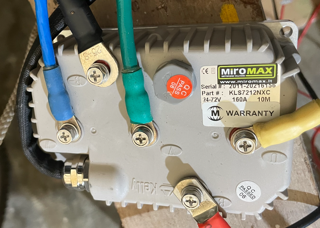
the controller actually converts the single phase DC into a three phase AC power. The motor came with a Kelly Controller for 48V and 150A max. It can be programmed with a laptop using Windows.
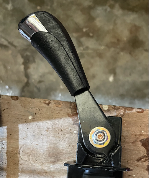
Throttle
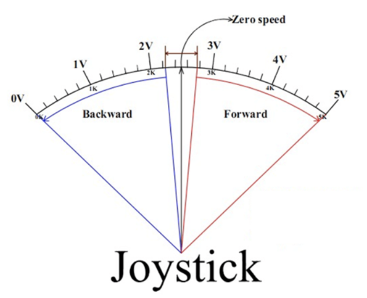
The throttle is a simple one with a hall sensor. It can be programmed for forward 0-max, which then requires another switch to go in reverse, or for zero in the middle portion similar to the usual controls on boats.
Battery
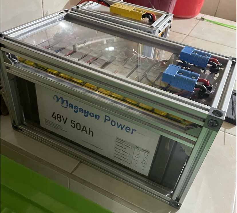
I already constructed one LiFePo4 battery with 48V and 50Ah in 2022, a second one was added in 2023. They have smart BMS that can be controlled via Bluetooth on the mobile phone. I bought the battery cells during COVID lockdown times, so options for getting them in the Philippines were limited. C factor for unloading is 1, meaning up to 50A can be drawn, C factor for loading 0.2, meaning it can be charged with 10A, resulting in a charging time of around 5 hours. No fantastic specs, but sufficient for the purpose. Combined they store 4.8 kWh.
A first test
The conversion
Re-building the Mechanics
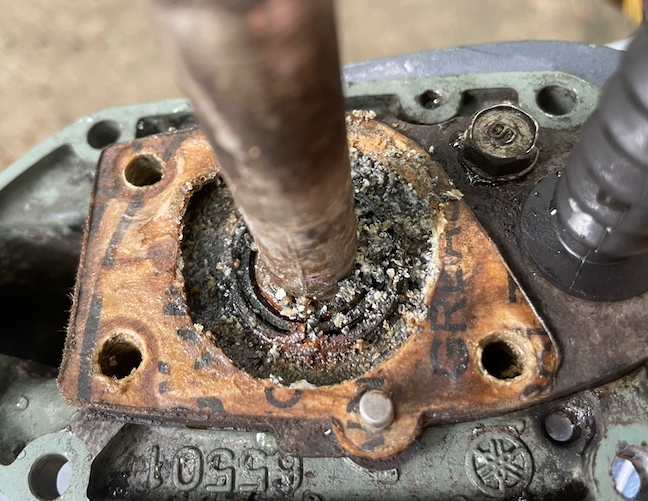
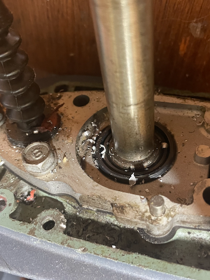
There was a bit of corrosion in the gearbox and the gearbox had water in the oil, so no doubt where the corrosion came from. So the first thing to do was to repair the gearbox, replace all oil seals, and some screws that were in bad condition. I did not want to repaint the whole motor, after all it is a prototype and might lead to disappointing results, so I just sand down the corroded parts. and applied epoxy primer.
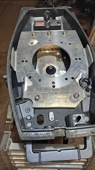
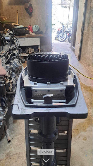
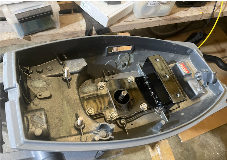
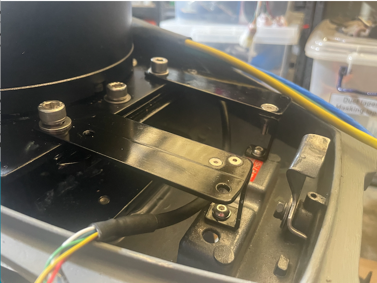
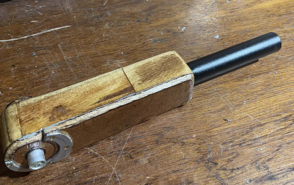
Fitting the Electric Motor
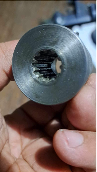
Next thing was to design and build a bracket to hold the electric motor in place plus an adapter to match the two different drive shafts. Since I don’t have a complete workshop to do more serious metal work, I asked Jeffry, a custom motorbike builder whom I met some years ago on the Motobuilt Pilipinas 2016 in Manila, whether he can do that. He had not worked on a boating project before and was quite happy to do something new. So I brought the parts to him before going to Europe in Summer 2023.
After the Europe trip and getting the motor from Jeffry, I was a bit busy with projects for making a living, so further work was shelved for a while. In the second half of October I slowly picked it up again.
Some more Mechanical Work
Last October 2023 weekend: When trying to turn the motor manually, the gearshift snapped out of gear and got stuck in neutral. Before bringing the motor to Jeffry for making the bracket, I had thought about removing the gearshift mechanism and fixing it in one gear since the electric motor can be reversed, but then I thought keeping options might make sense and had left the gearshift mechanism in. Obviously that turned out to be a mistake, I had violated the KISS principle. So I had no choice than to take the outboard shaft apart again. Which was good, because there were some metal shavings on top of the gearbox, which must have fallen in during the conversion.
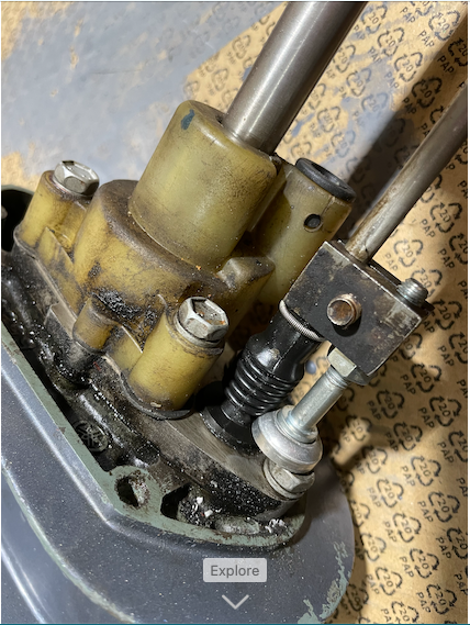
I also put back the water pump housing, but without impeller, to keep it in one place in case I want do experiment with water cooling the motor at some point. Last I removed the gearshift lever and the rod that connects it to the gearbox and locked the gear in engaged position with a clamp and screw so that it cannot jump accidentally in idle anymore.
October 29, 2023: After coating the aluminum parts with etch primer and then epoxy paint it was finally time for a test run and then the final assembly. Two additional simple brackets were needed for holding the controller and two more holes with threads in the bracket for mounting the contractor.
After a dry test run of 1 hour I removed the motor again to check whether the shafts and adapter are rubbing against the bracket, but all is good and the assembly could continue.

I also started designing the air cooling system today, ordered another small 48V axial flow blower in addition to the radial blower I have already, just to have some flexibility to play around with. Made the bracket for the blowers from aluminum sheet and fitted it in the top cover. This will be further documented once the blower arrives.
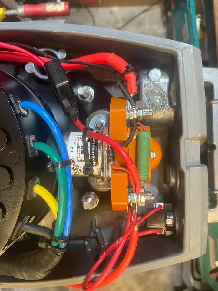
Remember the Good Old BOSCH Days – Electrics and Computer Stuff
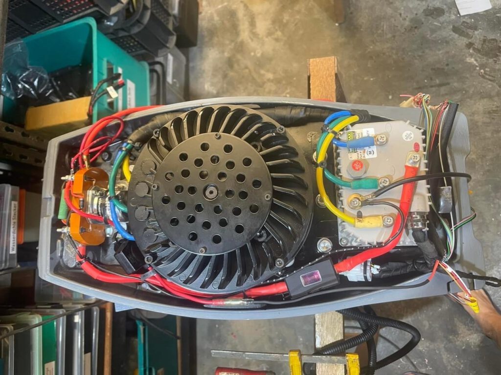
Wires, wire gauges, connectors, you need to know your stuff
It took half day to do the wiring. I could have done it faster, but that would have meant compromising on quality. A few things are still missing like the kill switch and the battery and control connectors. Also the whole air cooling system that still needs to be mechanically designed and constructed. But at least now it is basically fully functional, except for the joystick (see next section). It paid off that using the extremely long COVID lockdowns in the Philippines and online shopping I had assembled the proper tools and supplies like crimp pliers, terminals, cables of different gauges and heat shrinkable tube. Otherwise this would have taken a long time.
And I Thought I was done with WINDOWS for Good
November 1, 2023: It took half a day installing a virtual WINDOWS machine on my MacBook Pro and some time getting back to the basics – just to change one check box.
The Kelly controller came pre-configured with the most likely settings for a motorbike to allow the customers to speedily set up the bike and do the fine tuning of performance later, if needed. For a boat, there is one major difference. A motorbike has a twist throttle from zero to full speed, with a spring so it pops back to idle when you let go. A boat usually has a joystick that has zero in the middle, forward when pushed forwards and backward when pulled back. No spring. This means it has to be handled differently by the controllers. It can easily be changed in the controller, it is basically just one “Joystick” checkbox in the controller software, but for doing that a computer with the software running in WINDOWS has to be connected to the motor. The software is only available for WINDOWS and I only have migrated to Macs many years ago. So there was a bit of a problem. I tried to find a WINDOWS computer, but the only one I got did not give me administrator rights.
My computer skills are a bit rusty when it comes to non standard applications, so I got a bit worried. So it was either being a cheap second hand WINDOWS computer, or getting familiar with virtual machines and how to configure them so that they can work with the hardware components of the host computer. I did not really want to do that, but buying a WINDOWS computer for only one single purpose seemed to be too excessive in terms of resource use, so I went the difficult path.
I am glad to report that, after archiving some work files to make some space on my hard disk, within 3 hours I managed to 1.) download the VirtualBox, 2.) install it, 3.) download and install WINDOWS 10 (my first WINDOWS installation since 15 years), 4.) install and configure the USB drivers for VirtualBox, 5.) download and configure the USB- RS232 converter driver, 6.) install the controller software, 7.) test the whole thing and then 8.) connect to the motor and, 9.) change the checkbox to Joystick.. And voila, it all worked. What a Joy Ride. As Arnie said: Old, but not obsolete.
I must admit that nowadays it is a very different situation then when I underwent training as Informationselektroniker at BOSCH at the age of 17. Lots of help sites on the internet. 20 years ago this would have taken me 2 weeks involving lots of research and asking friends for undocumented tricks. See the video clip showing the correct functioning joystick.
The Kill (switch), a Bit of Frustration
The outboard motor kill switch arrived today. Good that I tested it because then I figured out that the contacts work the wrong way around. With the ignition key inserted it is open, key removed it is closed, shortcutting the ignition of an internal combustion engine. I need it the other way around. So I had to modify the switch. Another unpredicted work came up when the “Normally Closed” switch I ordered online arrived “normally open”. Damn, can those online sellers not read the order properly? So I had to re-order.
The right “Normally Closed” switch arrived a week later and the conversion was actually quite simple, remove the old switch parts, drill a hole of 7mm in the center of the base part, and the small switch I ordered fitted without any further modification needed. I am a bit worried about the small switch having to deal with 48V, 0.5A, although it is rated with 2A, but I better make a spare since they are not available in Yacht supplies.
Cool air
A friend , who had done a conversion of a 15hp motor before, reported that overheating was a serious problem and that they had to remove the motor cover during operation to avoid that. Moving enough cold air through the motor is therefore essential, the small covered opening on the top of the hood is sufficient for providing the air for the carburetor of an ICE, but not for cooling a 3kW motor. So bigger openings are needed. This is a challenge though, because rain – and spray water should not enter and reach the electrical parts. The difficulty is that the motor can be in many positions, down and upright for operation, and tilted when out of the water, and in addition it can be steered in both directions. So any hole, even with a grill cover, can let some water through sometimes. So what is needed is some sort of spray water separation after the air enters the hood. The question was, should I go for a suction based or pressure based system?
- Pressure based: Fan sucks the ambient air and pushes it into the motor. The air enters at outlets that should have covers to avoid water from entering. Disadvantage: The blower is very close to the water saturated air (e.g. during rain) – corrosion. Advantage: ???
- Suction based: The blower sits at the air outlet. Advantage: The air travels a long time so water can be separated before it reaches the blower. In addition, the blower is exposed to the air heated up by the controller and motor, meaning it has lower relative humidity. – Less corrosion. Disadvantage: Effect of temperature on the blower?
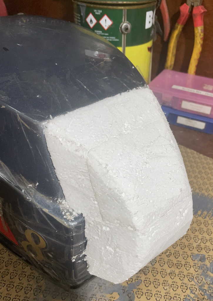
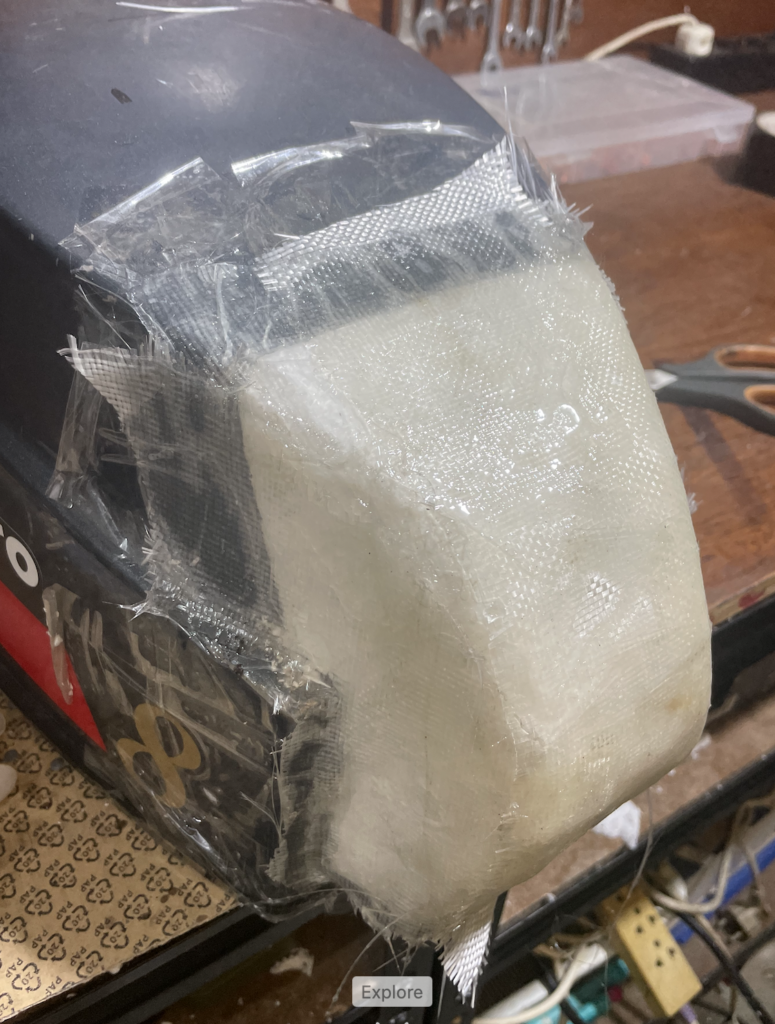
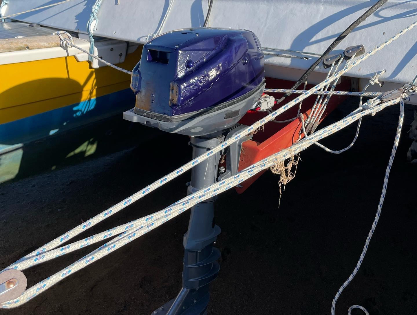
I therefore designed a suction based system with two 48V, 10W blowers, one axial and one radial to be able to play around with both types and placed them in the opening of the starting line at the front of the hood, which is not needed anymore. To avoid rain and splash water to enter the outlet, I then made a hood from fiberglass reinforced epoxy, after using styrofoam to shape it and packing tape to protect the styrofoam from the solvent of the epoxy and for easy separation of the piece once it was done.
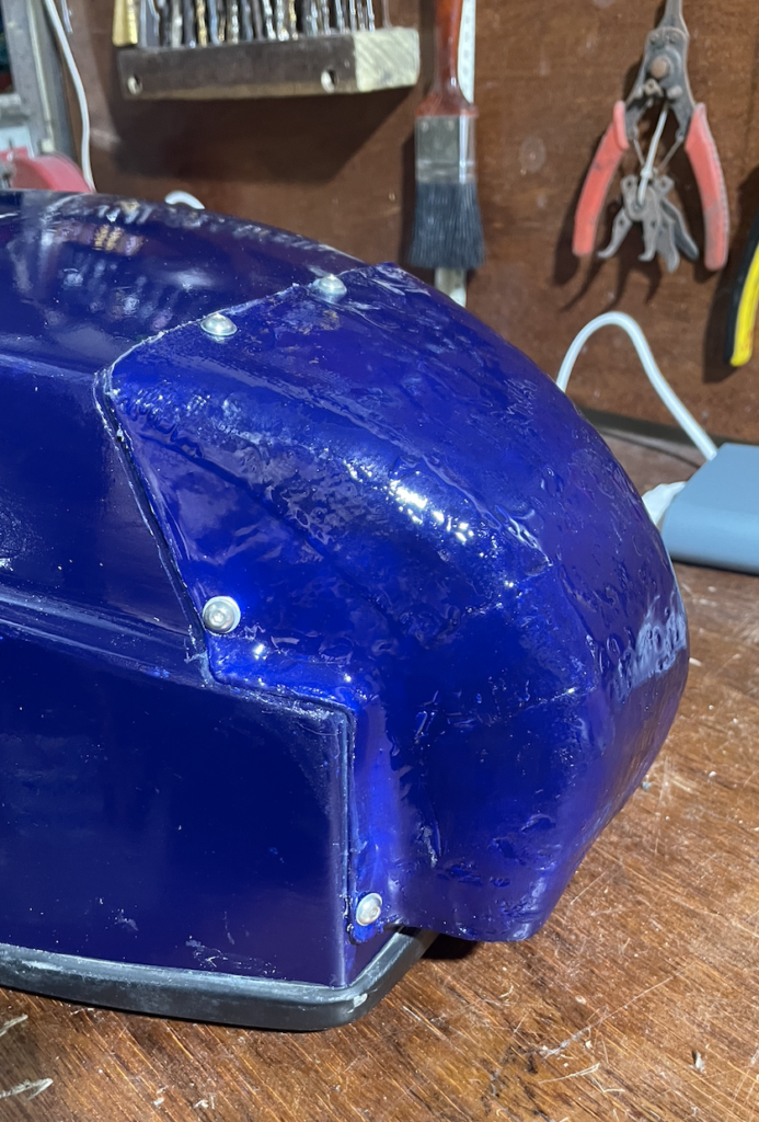
As air inlets I added inclining channels on both sides of the hood leading from the top downwards to the end of the motor. The air is sucked in through holes at the bottom, moves up in the channels, and at the top there are holes in the hood leading the air into a plenum chamber in the top of the hood. The chamber has two baffles forcing the air to turn and hopefully any water droplets to separate from the air by centrifugal force. After two turns the air then is led down at the back end of the hood deep into the motor housing to pass the controller and the back first and cooling it. It then progresses to the motor, before being sucked out and ejected by the blowers.
Initial testing of the blowers after assembly showed some good airflow. I did not spend much time on the finish, and used a dark blue paint that I had on stock. After all, it is a prototype and not a photo model.
Connections
First I wanted to have one connector for battery power and controls (Joystick, others). But then I opted for one battery connector and one control connector so that one could have options for controls, e.g. a twist throttle or a joystick. I modified a cheap motorcycle twist throttle so that it would work like a joystick, but the resulting resolution was too small. Started making the tiller replacement.
Build done and functional
November 14: Everything is assembled, connected and ready for testing in the water. Since i don’t have a controller yet, the fans are permanently on once the motor is turned on. Whether one or two fans can be selected inside with two switches.
The reverse sounds faster. I don’t have a tachometer so I can’t check it right now, need to get the torque meter first.
Motor settings
November 19, 2023: The tachometer arrived, so I could test the shaft and motor RPM. As the sound suggested, the motor was spinning faster backward than forward. A quick inquiry at Miromax to make sure that it has the same characteristics in both directions confirmed this, so it had to be the controller settings. I played around with settings of the joystick ranges for both directions and that did the trick. I then also limited the backwards speed to 80%. The motor easily lifts upwards when reversing too fast.
Control and Monitoring
Each of the two cooling fans consumes 0.2A, so a total of 0.4A equal to 20W. Not too much, but still, why run them when it is not necessary. So designing a little fan controller using an Arduino seemed to be cool, in particular because it can then also be used for monitoring and displaying process parameters. And, once I have it, I can also use it for other projects. The specs were quickly drafted:
- Fan voltage: 48V, switched by relais, modes of operation: 1.) both off; 2.) one running at temperatures between 40-50ºC; and, 3.) both running at temperatures above 50ºC.
- DC 48V to DC 5V converter for powering Arduino and display
- Measurements
- Temperature sensor for controller
- Temperature sensor for motor
- Temperature sensor 3 (reserve)
- Measuring battery voltage (V)
- Measuring current (A)
- Calculations
- Current Power (W)
- Calculation of battery load status (%) based on battery voltage using LiFePo4 battery characteristics function
- Display (Optional through connectors)
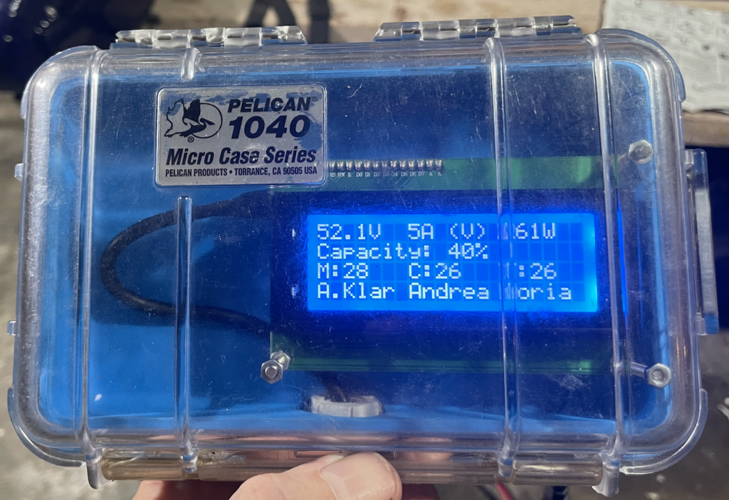
- Battery load status in percent on a 4 digit 7 segment display
- All process parameters and warnings on a 4 line / 20 character LCD display
- Others
- Waterproof
Not yet sure how to measure the current. I don’t want to use a shunt because of the voltage drop (Kleinvieh macht auch Mist). The contact less transformer sensors only work with AC voltage. Things to explore:
- Hall sensor and own calibration (one is ordered for testing)
- Using a transformer sensor at one phase and extrapolating (I will have to get into the details first)
It is straightforward. Except for an Ampere sensor and a relays card I had all components in my little electronics lab. Most of the libraries I could recycle from previous projects. For the second time I used the free software KiCad for the schematic diagram, I find it a lot easier than EAGLE for the occasional work.
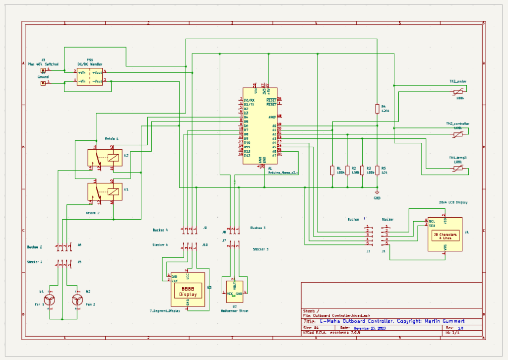
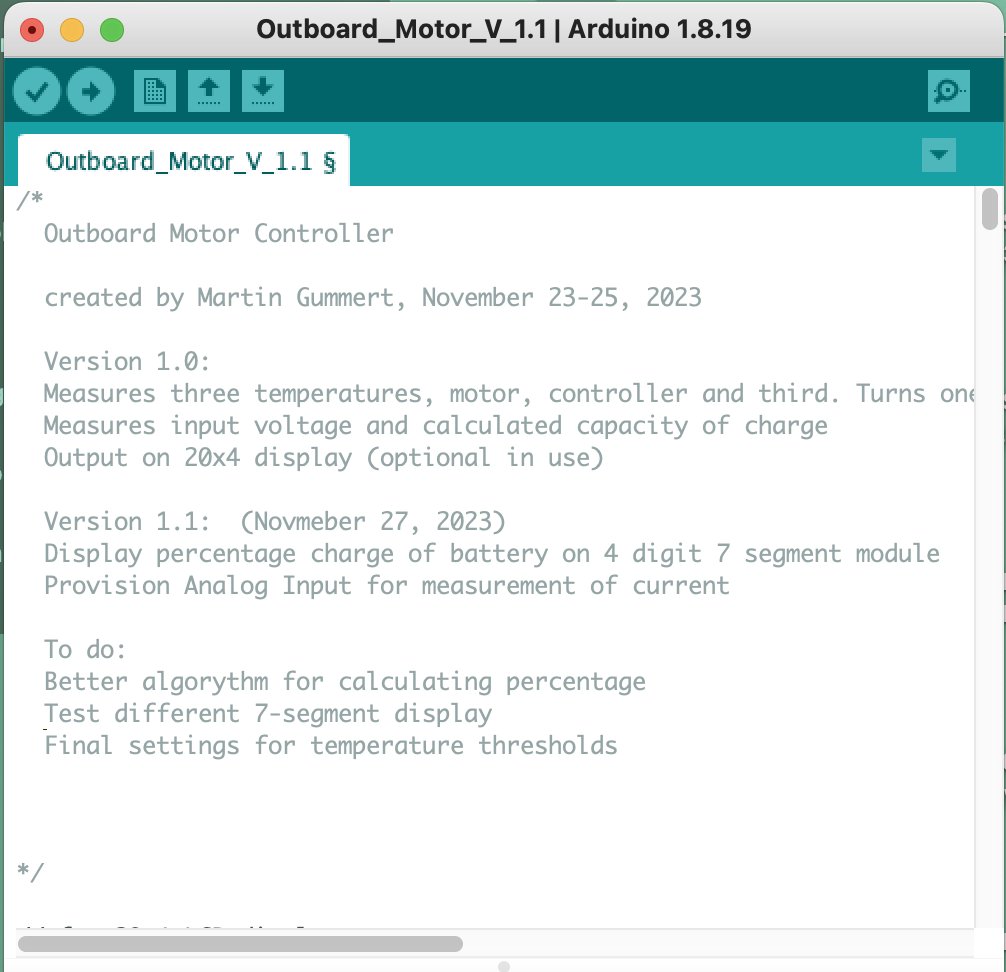
Design, construction, programming and testing of the controller took 3 days. For now, the prototype rests in a TEKO enclosure and a lot of silicone and heat glue provides waterproofing. The Display is designed to be detachable so that it can be used for performance checking, error search and optimization, but is not needed in normal use. I had an old Pelican Box for handphones, which had stared leaking. I fixed the leak and converted it to house the LCD display.

November 27, 2023: Tested all and everything works as specified. Still waiting for the relais board to power the fans.
November 29: The relays arrived, which caused some frantic last minute tinkering to install the controller in the motor housing before going to Zambales tomorrow for testing the motor on the boat. It worked out in time, and dry testing in the workshop showed that the controller works as designed. The only thing missing is the measurement of current because I got the wrong (digital) hall sensors and had to order analogue ones.
December 10, 2023: It took some time to work out current measurement, which is necessary for the calculation and display of motor power. I exprimented with different sensors and ended up using the ACS758 Hall Effect based linear current sensor IC, 100A version. It has only 100µΩ, power loss is only 0.36 W. Developed and integrated the code today and tested the sensor. It works.
Wet Testing
We spent an extended weekend from November 30 to December 4 at Sundowners Villas in Zambales to finally test the electric motor under real world conditions and to establish some parameters like temperature thresholds for the fan controller. Test objectives were to: 1.) Evaluate how the motor works on Magayon II, in particular how the different power and torque characteristics compared to a ICM work on a boat; 2.) Determine the maximum speed; 3.) Measure power at different boat speeds at different motor speeds (just above idle, slow cruising speed, fast cruising speed) and calculate ranges per battery load; 4) Determine maximum current to see whether one battery is sufficient (50A max) or whether both need to be operated parallel; and 5.) establish the key parameters for configuring the fan controller.
It was springtide, so loading the motor on the boat could be done easily with dry feet. Unfortunately we found some major structural damage on the aft cross beam, and some signs of vandalism at the boat. So testing the motor had to be done carefully to not overload the weakened cross beam.


The plan was changed. Gentle testing this time only and then we’ll go to Lake Taal for some more serious testing using an aluminum fishing boat.
The testing worked out beautifully. All components of the motor work according to the design specs. The full torque at low revs works out well and at cruising speed the motor only consumes 30 amperes (1.44kW), which will give us much better range than expected. Around 3 hours or 7.5 hours at low cruising speed.
Video of the testing.
The controller parameters need some fine tuning, in particular the ramp up time when getting into gear, bit that is peanuts. I did that on the parking lot of Sundowners, now it needs to be tested again. Due to the damage on Magayon II we did not push it. Will do some more testing, maybe next weekend at Lake Taal.
More Testing
December 9, 2023: Some more testing of the motor on Lake Taal with an aluminum fishing boat. It went well, the maximum current was 60A at 50V battery voltage, within the limit of one battery or equivalent to 3kW. Motor and controller temperatures did not exceed 56ºC at any time. So given the slip of the propeller in the water the motor does not reach the potentially critical 4.1kW at lower motor speeds, which means that it always operates within the 3kW nominal power, eliminating the risk of overheating.
Cost
How much did it cost? Total project cost was US$ 2,000 including motor, display and power cables, shipping of components but without accounting for my labor. A commercial motor with similar power costs between US$ 3,000 and 5,000, and there is big potential to reduce the cost of the conversion:
- The bracket and shaft adapter constituted a major cost component. This can be reduced significantly.
- Sourcing the motor and controller directly in China can reduce those component cost by at least 30%
- Systematically reducing other components cost. For the Arduino for example a clone could be used.
Durability has to be tested. Total efficiency will also be lower than with a commercial unit that was designed and optimized for highest efficiency of all components.
Still to be Done
- Integration of the electrical components into Magayon II (See Electric Magayon II – Deployment).
- Efficiency calculations based on long term operation
- Test durability
- Test the motor at heavy rain, check that no water enters in any position it could be.
New Projects
Convert the 2.5hp Mariner outboard with a smaller electric motor, around 1.5 kW.